by Renato Croci
These special kind of radars, of great importance for the Earth observation from space, are anyway almost unknown outside the circle of the specialists. Aim of the present article is explain their operating principle and applications
Note: full understanding of this article requires, as a background, knowledge of radar basic concepts, as explained in the Radar Basics article.
What could be the purpose of a radar-altimeter, i.e. a radar which measure the heigth of the satellite carrying it? To reply to this question we shall reverse the underlying point of view: if the satellite orbit is known - and, today, very accurate measurements are available - such an instrument can provide the elevation of the surface below. If the instrument is capable (at least, over 'relatively' flat surfaces like oceans) of resolutions and accuracies in the order of centimetres, then its data becomes extremely useful for a large number of applications.
The sea level is, in fact, far from being constant: its level is influenced, both over space and time, by tides, anomalies of the gravitational field, ocean circulation and submarine topography.
A radar-altimeter is a radar which, thanks to a very high range resolution, is able to detect, on a global basis, these (small) variations of the (average) sea level. Additionally, from the collected echo data it is possible to extract information about wave heigth and wind speed at sea level: these data have also significant scientific and applicational importance.
The first 'operational' radar-altimeter flew on 1978 onboard the NASA's SeaSat satellite (unfortunately, lost after only 100 days of operation due to a failure in the electrical power control system). Radar-altimeters are embarked onboard the European ERS-1 and ERS-2 satellites, and on the US/French Topex; other radar-altimeters are under development or manufacturing for the next generation Earth observation satellites.
The sea-level profiles generated by radar-altimeters (which can be used to generate global-scale maps), can be properly processed to separate their static and dynamic contributions, providing the following information:
We will try below to provide a brief explanation about the mechanisms allowing these sensors to provide the above mentioned data, with the caveat that the discussion applies only to the special (but, by far, the most common) case of an altimeter "nadir-pointing" (i.e., observing straight below) and "pulse limited", i.e. for which the illuminated surface il limited only by the range resolution and not by the antenna beam aperture (see the description of system geometry below) operating over ocean surfaces.

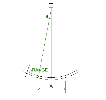
FIG. 1 - OBSERVATION GEOMETRY
The system geometry is sketched in fig.1: delta-range is the range-resolution cell (related to the signal bandwidth); if the antenna beam aperture is grater than +/- theta (achieved with very small range-resolution cells, corrensponding to time resolutions in the order of nanoseconds), the altimeter is called pulse limited, and the incoming signal illuminates a circular surface of diameter A. Then, as the wavefront moves forward, the illuminated surface becames an enlarging ring, growing till the limit of the antenna beamwidth.
For such a system, the echo from an ocean surface is described by an analytical model called the Brown model. An example of Brown echo waveform is shown in fig.2.
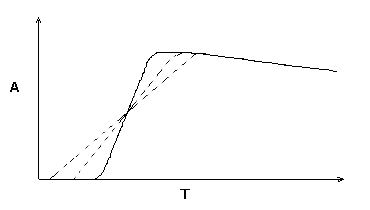
FIG 2 - BROWN ECHO
The position of the rising edge centre corresponds to the (average) distance of the sea surface. Without entering into the analytical model it is possible to show how the slope and the amplitude of the echo are related, respectively, to the wave heigth and to the wind speed.
The solid line in fig.2 represent a "flat sea" situation. In presence of waves, the signal wavefront will initially interest only the wave tips, then gradually extend to all the surface, within a time proportional to the wave heigth.
This results in a reduced slope of the echo leading edge, corresponding to the dashed lines in fig.2, for increased wave heigth. This can be used to retrieve the wave heigth information.
The effect of the wind over a sea surface is to increase its roughness, in a way proportional to the speed of the wind itself.
A perfectly planar surface behaves, with regard to electromagnetic waves, like a mirror: the impinging energy is almost totally scattered at an angle -a (being a the angle between the direction of incidence and the perpendicular to the plane). In the case of observation at nadir (i.e. perpendicular to the plane) the greatest part of the energy in then scattered back toward the transmitter.
If the sourface is rough, the "radiation backscattering lobe" of the backscattered signal is widened, and the energy is then distributed over a larger angle around the zenith, then decreasing the amplitude of the peak of the reflection lobe. The surface reflectivity (ssigma-0) decreases. The widening of the reflection lobe for a source at zenith is depicted in fig. 3.
The observable effect is then a change of amplitude: with increasing wind speed, the amplitude of the echo signal decreases. With proper calibration of the radar-altimeter, IT is then possible to extract the wind speed information.
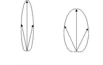
SMOOTH SURFACE ROUGH SURFACE
FIG 3 - BACKSCATTERING DIAGRAMS FOR ZENITH OBSERVATION
To be able to fit the Brown model with accuracies in the order of few centimetres, the range resolution of the radar shall be in the order of tens of centimetres. This requires the use of extremely large signal bandwidths, (hundreds of MHz) which are not easy to handle. On the other way, a radar-altimeter must not analyse the whole PRI, but just the small "window" where the surface echo is present. The system shall, of course, be able to track the echo range, moving the analysis window to keep the echo centered within it.
The small range window of interest allows to employ a special technique, called deramping, to use wideband transmitted signals while keeping the receiver bandwidth low (avoiding the use of large percentage bandwidths in the intermediate frequency section, with the consequent distortion problems and the need to use very high-speed Analog-to-Digital convertes and digital signal processors).
The deramping technique foresees the use of a chirped (linear frequency modulated) transmitted signal: in the first stages of the receiver, the received signal is compared in frequency (using a mixer) with another, identical, chirp signal (usually shifted in frequency to have the resulting difference frequency around a non-zero carrier frequency in order to allow proper processing at intermediate frequency).
The situation (for a single-point-target) is depicted in fig. 4.
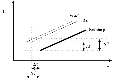
FIG. 4 - DERAMPING OF CHIRP SIGNALS
It can be seen that a shift in the return echo wrt the reference signal corresponds to a proportional shift of the difference frequency. The time shift between the echo and the reference can be determined by measuring the carrier frequency of the resulting pulse.
The operation for single-point-targets can be easily extended for the case of complex targets like Brown echoes from an ocean surface. A complex target can be considered as composed by several elementary targets, each producing a chirp echo with its proper delay: after the deramping process, each one generate its own difference frequency.
As a result, the output of the deramping process is no more a tone, but a spectrum with an amplitude distribution as a function of the frequency which mimics the time distribution of the Brown echo, and which can be reconstructed using standard signal analysis techniques (Fourier transform).
The generic block diagram of a radar-altimeter is depicted in fig.5.
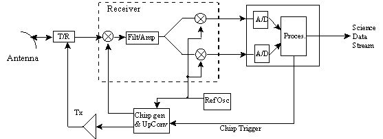
FIG 5 - RADAR-ALTIMETER GENERAL BLOCK DIAGRAM
The "Chirp Generator & UpConverter" generates the chirp signal which, after amplification in the transmitter (Tx) is sent to the antenna via the transmit/receive switch (T/R).
The received signal, inside the receiver, is compared with the deramping reference chirp, also provided by the "Chirp Generator & UpConverter". The resulting spectrum is then amplified and filtered, then coherently demodulated extracting its sine and cosine components. These are converted into a digital form by the A/D converters and sent to the signal processor, which performs the Fourier transform, the echo integration and possible other operations. The resulting data are then available at the system output for transmission to ground.
Additionally, the processor controls the synchronisation signals for the generation of the transmission and deramping chirps ("Chirp Trigger"), in order to keep the deramping reference overlapped to the received echo.
The radar-altimetric missions carried out in the last years (from SeaSat to GeoSat, ERS-1/2 and Topex) have provided a significant amount of data of remarkable scientific importance. The last generation of radar-altimeter exploits accuracies in the order of few centimetres.
The current trend, more than toward a further increase of the accuracy, is to avoid the need for external corrections (for example, using a dual-frequency scheme, it is possible to compensate for the ionospheric delay -which is frequency dependent - without need for external correction data).
Other possible lines of development for the future are:
Last updated