Any electronic device at a temperature greater than the absolute zero is affected by noise.
Such noise is called white, i.e. the power is homogeneously spread over the spectrum (defining a Power Density, in W/Hz o in dBm/Hz).
The total noise power at the output of an amplifier
is proportional to the noise bandwidth of the amplifier
itself. The noise bandwidth is equal to the integral of the frequency response.
As a first approximation, it can be considered equal to the signal
(-3 dB) bandwidth of the amplifier itself.
The Noise Figure, accounts for the grater noise of the device wrt the ideal case. F = 1(0 dB) for an ideal device, F > 1 ( > 0 dB) for real devices.
The noise power at the output of a chain of cascaded stages is given by:
Pn = K * T * G * B * F
where:
Pn: output noise power (in W)
K: Boltzmann's costant
T: Absolute temperature(in °K)
G: Power gain of the chain (linear)
B: Chain noise bandwidth (in Hz)
F: Noise Figure (linear)
Expressing gain and noise figure in dB, the bandwidth in dBHz (= 10*log B(Hz)), and remenbering that, at ambient temperature (27°C = 300 °K) the value of KT is -174 dBm/Hz:
Pn(dBm) = -174 + G(dB) + B(dBHz) + F(dB)
The overall noise figure of n cascaded stages having gain Gn and noise figure Fn is given by:
F = F1 + (F2 - 1) / G1 + (F3 - 1)/G1*G2 + .... + (Fn -1) / [G1*G1*..*G(n-1)]
Warning!: Both G and F are expressed in linear form, not in dB!
To optimize the noise performance of a chain, the bandpass shall be the minimum needed to support proper amplification of the signal.
It is important to select the first stage for the minimum possible noise figure.
The contribution to the overall noise figure of the stages downstream the first one is reduced proportionally to the gain of the upstream stages. For this reason it is a good approach to have an high gain first stage, in order to reduce the contribution of the other stages to the noise figure.
Dynamic is generally defined as the ratio between tha maximum and minimum useful signals. These two terms can be defined in different ways:
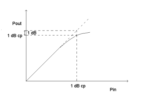
When an amplifier enters saturation, its gain is reduced wrt the linear conditions. To characterize the maximum working signal of an amplifier, the 1 dB compression point is often used. It represents the level for which the gain is reduced by 1 dB wrt the linear conditions.

Another way to characterize the non-linearities of an amplifier references to the spurious frequencies (harmonics and intermodulation products) generated due to the non-linearity.
Usually, in analysing receiver chains, it is not of particular interest to characterize the harmonics, being them, due to the operation on a carrier frequency, laying outside the signal bandwidth, and then being easily removable by filtering.
The common approach relies, instead, on intermodulation products, particularly on those of the 3rd order, defining a 3rd order intermodulation intercept point (3rd order IM IP). This because these product can fall inside the receiver bandwidth.
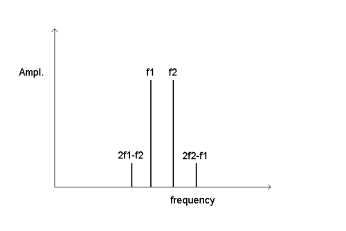
When two signal at frequencies f1 and f2 are applied to a non-linear device, intermodulation products (called 3rd order product, being due to the beating of a 1st order and a 2nd order product) at frequencies 2*f1-f2 e 2*f2-f1, appear.

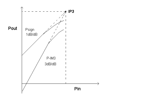
Plotting the levels of output signal and intermodulation products versus the input level, it is possible to see that the signal increases (in dB) with unitary slope, while the intermodulation products increase with a slope of 3dB/dB.

Estrapolating the curves, it is possible to determine the (teoretical) point at which the level of the 3rd order products would equal the signal level. This point is called the 3rd order intermodulation intercept point (IP3).
Knowing that 3rd order products grow with a slope of 3 dB/dB (vs the 1dB/dB of the signal) it is possible to compute the IP3 from the knowledge of signal and intermodulation levels for a single value of the input power:
IP3 = ( 3 * Psign - Pim3 ) / 2
(in dBm)
Viceversa, from the IP3, it is always possible to compute the level of the 3rd order products for a given level of the signal.
Note: for many active devices, the IP3 is between 10 and 15 dB above the 1dBcp (typ. 13 dB).
The overall 1 dB compression point, as the 3rd order IP for a cascade of n stage (each having gain Gn and P1dB - or IP3- Pn) is given by:

Warning!: Both G and P are in linear form, not in dB!
Last Updated